Reverse Camera Delay
A little side-quest in analogue electronics: a delay-on circuit for the reverse camera in the car. It switches the camera on a second or so after the reverse lamps come on, so a short tap of reverse does nothing.
Why
An interesting little side-quest: a tiny circuit with a real job, small enough to design, draw and understand completely, and built from common parts I already had.
How it works
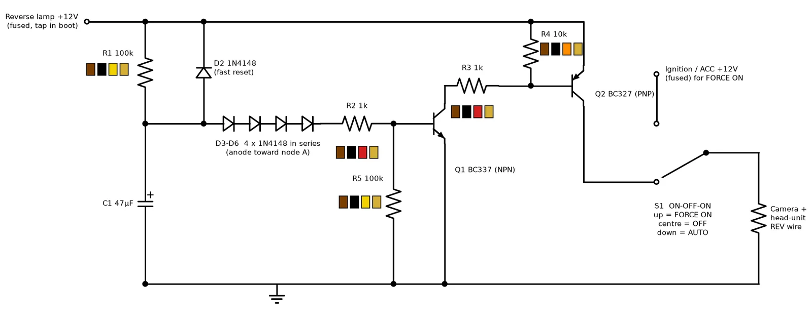
- A 100k resistor charges a 47 uF capacitor from the switched reverse-lamp feed. When the lamps go off, a diode empties the capacitor quickly, so the timer is ready again straight away.
- A chain of four small diodes in series stands in for a voltage reference. Together with the base-emitter drop of the first transistor, they hold it off until the capacitor reaches about 3.2 V, which takes roughly 1.5 seconds from a 12 V feed.
- That NPN transistor then switches on a PNP transistor high on the supply side, which powers the camera and the head unit's reverse wire.
- A 100k resistor holds the first transistor firmly off until then, and a pull-up holds the second one off.
- A three-position switch selects auto, off, or forced on from the ignition feed, so the camera can still be used when the car is not in reverse.
It is deliberately crude: the delay shortens a little at the higher voltage of a running car and the diodes drift with temperature, but a second either way does not matter for this job. Other versions with a comparator and a proper reference were drawn up for comparison, and this is the simple one that is built.
Under the hood
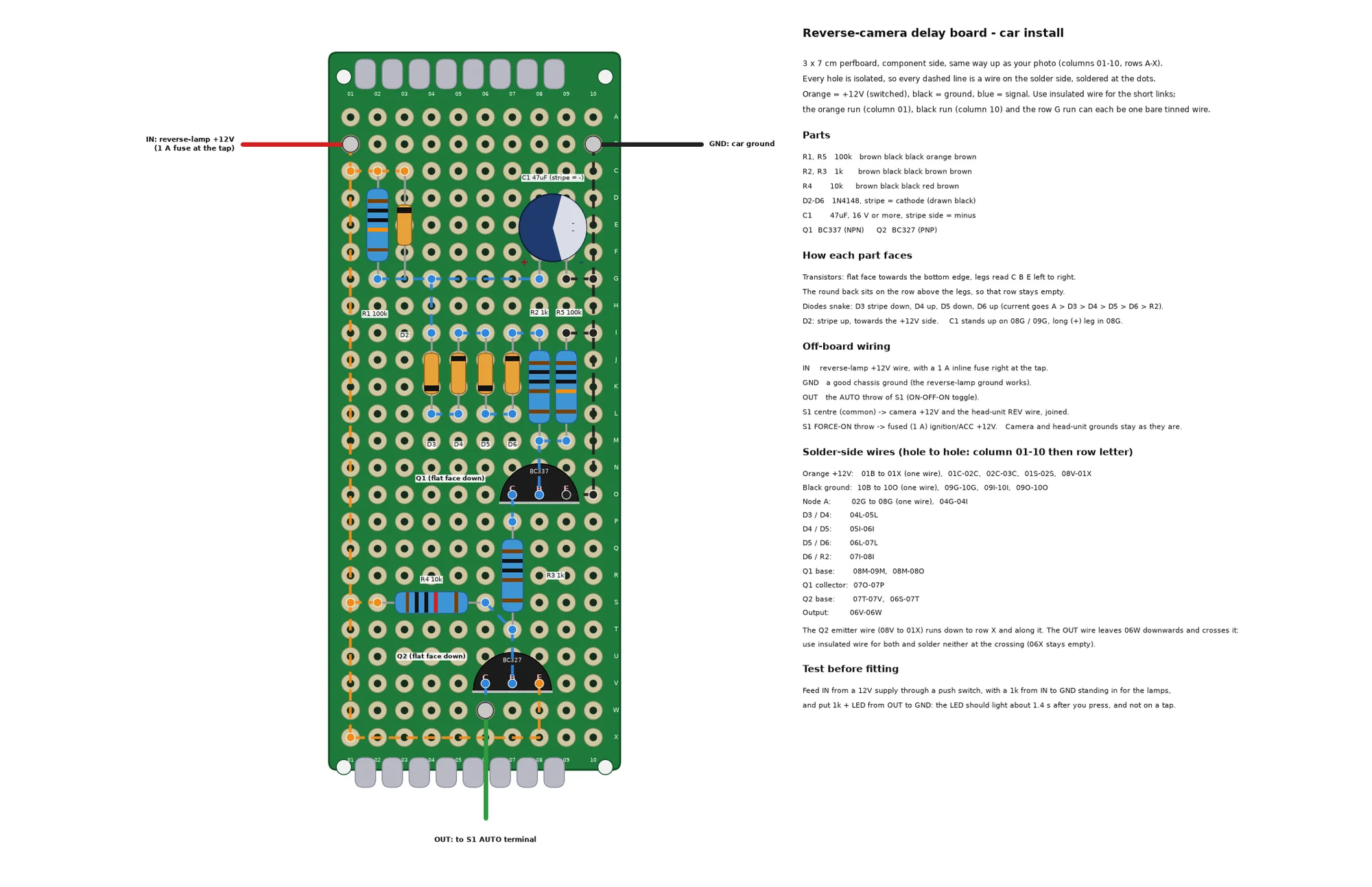
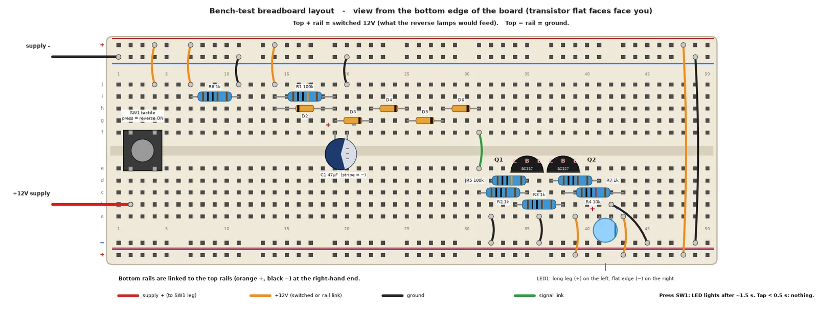
- Every drawing is generated by Python with schemdraw and Matplotlib: the schematic, a breadboard layout for testing and a 3 by 7 cm perfboard layout for the car.
- A shared layout engine places the parts and checks every leg against the schematic's connections before it draws, so a layout cannot quietly disagree with the circuit.
- The perfboard sheet lists the parts, which way each one faces, every solder-side wire and a bench test to run before fitting: feed it 12 V through a push switch and the LED should light about a second and a half after the press, and not on a short tap.
A hobby design for one car. Test it on the bench before fitting it.